- Other Fluke companies:
- Fluke
- Fluke Biomedical
- Fluke Networks
- Fluke Process Instruments
Steps to determine if the size of your source is too small
1. Introduction of Three Methods
Knowledge of size of source is important for your infrared thermometer calibration. You should use this knowledge in determining a proper size for the thermal radiation source used for the calibration. The three methods to study the amount of source are listed below.
- Field-of-view Test
- Field-of-view Specification
- Sweep
2. Description of Methods
2a. Field-of-view (Target Size) Test Method
The field-of-view or target size method is described in ASTM E1256 and VDI/VDE 3511 Sheet 4.3. The methods described in these two standards are nearly identical. One major exception is that the VDI/VDE method calls for the use of a cooled aperture. In a nutshell, these methods use an aperture of variable size. As you change the aperture size, you observe the temperature readout of the infrared thermometer. You make a determination of enough size, when you observe an acceptable amount of change as the aperture size increases.
2b. Field-of-view Specification Method
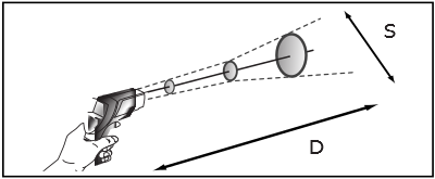
This is not a test method at all. It relies on the information provided by the infrared thermometer manufacturer. The information provided by the manufacturer is termed by IEC as “field-of-view”, “distance ratio”, or “size-of-source effect”. Manufactures will commonly include this type of specification in terms of D:S (distance to spot ratio), a distance and spot size diagram, or measuring spot charts. A ‘D’ to ‘S’ ratio specification generally gives the best case data. You are better off using data from a distance and spot size diagram, as this will give more realistic data of the field-of-view at a specific measuring distance. For instance, in Figure 1 an infrared thermometer with a D:S ratio of 12:1 may have a field-of-view of 38 mm at a measuring distance of 300 mm (a ratio of 7.9:1).

Figure 1. Distance and spot size diagram
The field-of-view information provided by manufacturers pertains to how much field-of-view is within a given diameter at a given measuring distance. However, this does not mean all of the signal received by the infrared thermometer is within the field-of-view diameter or ‘spot’ diameter. Usually, it means 90% of the field of view is within this diameter. To be on the safe side, you should use at least three times the field-of-view speciation for your source size. For instance, you are calibrating an infrared thermometer with a field-of-view diameter of 45 mm at a measuring distance of 200 mm. You should use a source with a diameter of at least 135 mm for the calibration.
2c. Sweep Method
The third method is to use sweeping. In this method you place the infrared thermometer at its measuring distance. You should move the infrared thermometer in the ‘X’ and ‘Y’ directions (right and left, up and down). While this is being done, the readout is observed. If the source is large enough, you should see the infrared thermometer readout plateau at a certain value for part of the sweep. If the source is too small, you will see the infrared thermometer readout peak. In other words, as you are sweeping, the infrared thermometer readout will reach a maximum value, then quickly drop off again.
3. Which Method is Better?
This is a question with a qualified response. It really depends on what you are looking for from the result. If you want a very precise metrological result describing the field-of-view at different diameters that allows you to precisely determine the uncertainty, then the field-of-view Test Method is the best method. However, it is very time consuming and requires additional equipment. Using the field-of-view specification is the quickest. However, you are really at the mercy of the infrared thermometer manufacturer properly specifying the field-of-view. The sweep method is a good compromise. It is based on an in-situ measurement without any extra equipment and is based on a measurement of temperature. It is an extra test, but it is a quick test. In reality, you should perform a similar type of procedure when you are aligning the infrared thermometer.
4. A Practical Example
For this example, an infrared thermometer with a spot size of 38 mm at a measuring distance of 300 mm is used. The measuring distances used for these tests are 300 mm. The nominal temperature of the source is 200 °C. The infrared thermometer used has a D:S specification of 12:1.
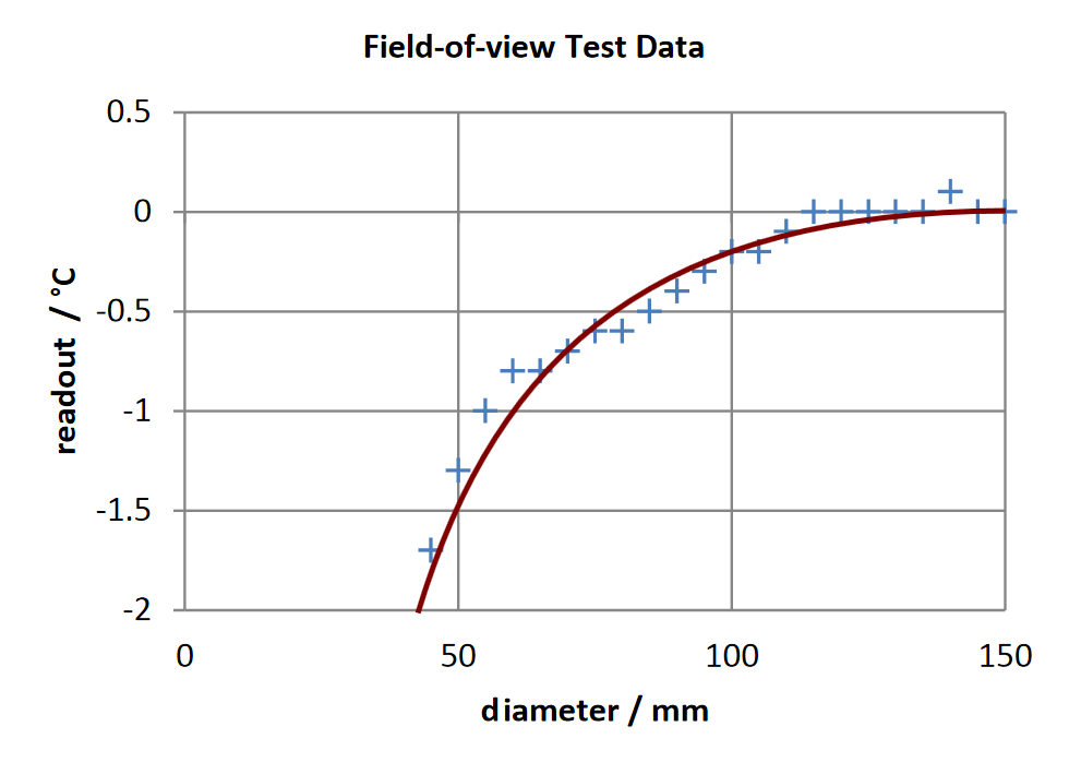
First, a field-of-view test was performed. A 4181 was used as the source, and an iris diaphragm was used for the variable aperture. The results of this test are shown in Figure 2. This particular infrared thermometer has an accuracy specification of ±2.0 °C at 200 °C. If we would like our uncertainty due to size of source effect to be less than 1/4 of this of this accuracy specification, then we would need at least 85 mm of source to perform this calibration.

Figure 2. Results of Field-of-view Test Data
For the field-of-view specification method, the distance and spot size diagram as mentioned above was used. According to the diagram, the infrared thermometer has a spot size of 38 mm at the measuring distance. Using the three times rule, we would need a source diameter of at least 114 mm.
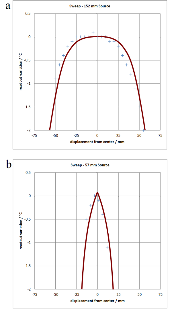
For a typical sweep test, the infrared thermometer can be swept in an angular direction while observing the readout. For demonstration purposes, the infrared thermometer was attached to fixturing. The infrared thermometer was radiometrically centered on the vertical axis. Then the infrared thermometer was moved along the horizontal axis, and the readout temperature was observed. 152 mm and 57 mm sources were used for this test. Plots of both sets of data are shown in Figure 3. Clearly, the 152 mm plot shows a plateau and the 57 mm plot shows a peak. Table 1 shows a comparison of the results of all three methods.

Figure 3. Results of Sweep Test Data
|
Test
|
Needed Diameter / mm
|
|
Field-of-view
|
> 95 mm
|
|
D:S
|
> 114 mm
|
|
Sweep
|
> 57 mm
152 mm OK
|
Table 1. Comparison of Methods
5. Conclusion
All methods agree that the source for this particular infrared thermometer calibration must be at least 85 mm in diameter. The field-of-view test provided the most precise answer, but was also the most cumbersome to perform. The field-of-view specification method showed that at least 114 mm was needed. This is a safe answer, as it greater than the minimum diameter reveled in the field-of-view test. The sweep method correctly showed that the 57 mm diameter was too small and the 152 mm diameter was sufficient. Although the sweep test did not give a precise cutoff point on how much source was needed, it did give a pass / fail indication of sufficiency for source size. It is a real in-situ type test where you don’t need any external equipment.
Links
Determining size of source for handheld infrared thermometers
Standards for radiation thermometry
How to calibrate an infrared thermometer (web seminar)
Infrared calibration web seminar (Spanish)
- Login to post comments
- Printer-friendly version »
- Home
- Products
- New Products
- Electrical Calibration
- RF Calibration
- Data Acquisition and Test Equipment
- Temperature Calibration
- Humidity Calibration
- Pressure Calibration
- Flow Calibration
- Process Calibration Tools
- Calibration Software
- Service and Support
- All Calibration Instruments
- Handheld Test Tools
- Purchase Info
- News
- Training and Events
- Literature and Education
- Service and Support
- About Us


Comments
Hi Ray,
This is a simple test to see if one has enough source. Likely it is used with a less precise instrument. For a more precise instrument, one should use Field-of-view Method. Table 1 kind of points this out, but it is good to emphasize this point.
There is a history of calibrating radiation thermometers with apertures that are too small. For instance, if an instrument with a field-of-view of 20 mm (98%) is calibrated using a 20 mm aperture, the 2% of the radiation coming from the aperture can cause large errors if the aperture is not controlled or if the RT is not properly aligned.
Having an oversized source is ideal but not always possible.
Frank:
A very good topic to bring up, Thanks, this is the perfect place for it. But the subject is not a simple one, unfortunately.
If one wishes to have a unit calibrated with a quantifiable uncertainty, eg. n number of degrees within an x% confidence, as you will learn in your QA courses, then you have to be very careful.
Even more important when one uses a device with a "generous" target-size effect on a less than generous target in outside measurements, ie. smaller rather than larger.
My ultimate criteria for the significance of such a test is what amount of measurement error is introduced by using the different criteria for target size effect, first in actual calibration and second when measuring some real-world objects.
For instance, most LW IR thermometers have an output that is nearly linear in error with a change in target temperature. So, a +1% variation in size-of-source effect, from 90% to 91% should result in about a and area viewed + 1% difference in temperature reading irrespective of the target temperature. But from 90% to 95% is a +5% temperature reading difference, leading to a +5% increase in reading from the same source!
It's all spelled out in the error table in ASTM E1256. I think there is a copy of the table online somewhere. I'll have to come back with a link another time.
More later.