- Other Fluke companies:
- Fluke
- Fluke Biomedical
- Fluke Networks
- Fluke Process Instruments
How to calibrate an oscilloscope
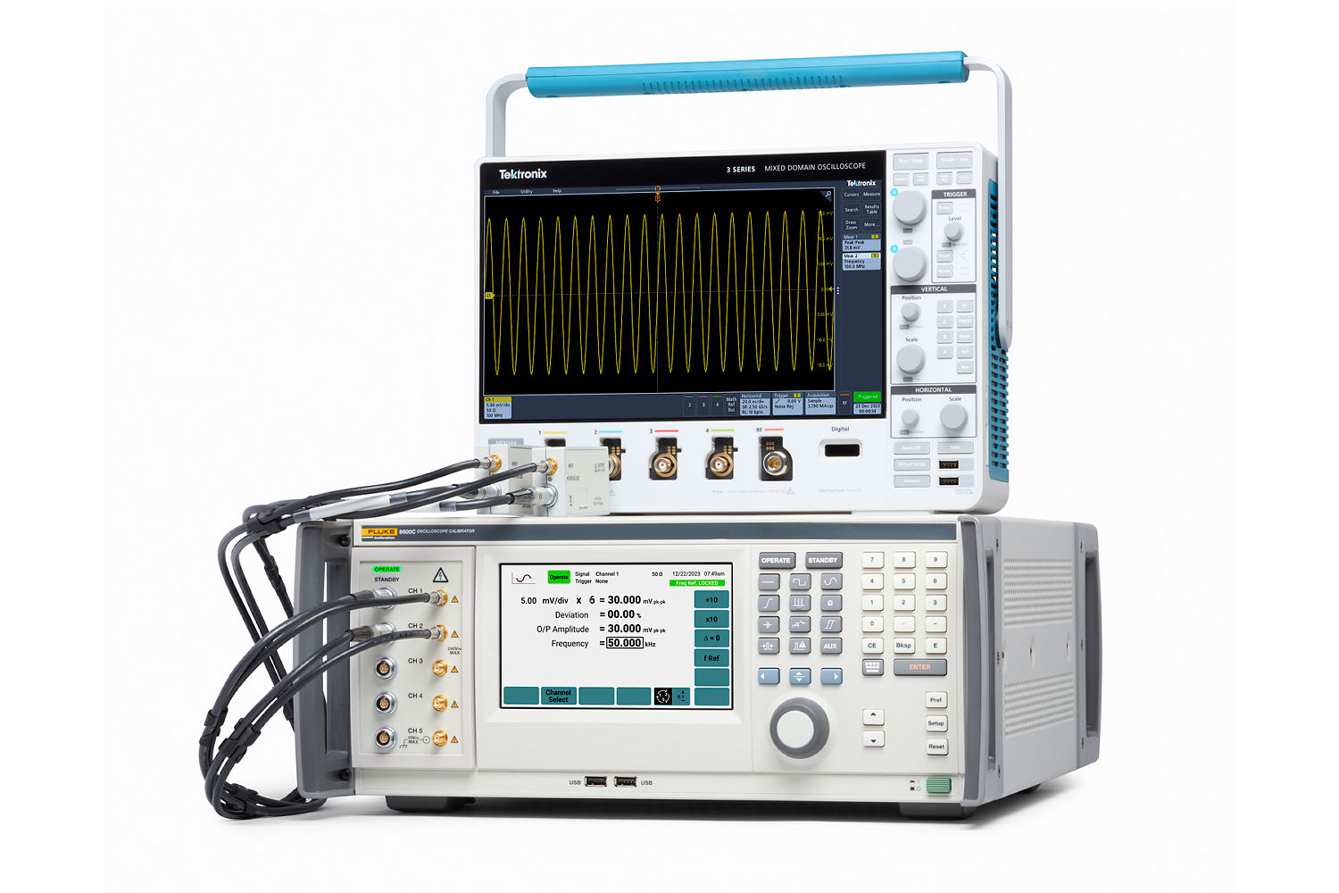
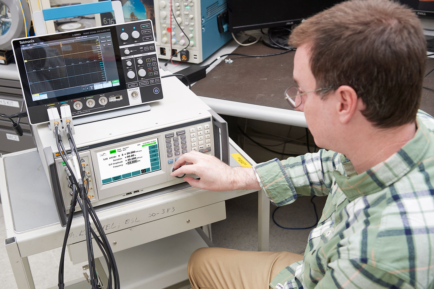
Oscilloscopes are extraordinarily complex instruments. At their most basic level, they provide easy and direct access to waveforms then make both qualitative and quantitative analysis of that information. But each oscilloscope also offers users the flexibility to deal with a wide range of functions, frequencies, and voltages in one tool. That makes calibrating them more complicated, yet even more important.
Calibrating an oscilloscope is essential to ensure accuracy and reliability of its measurements. Over time the performance of an oscilloscope can drift leading to inaccurate measurements. This drift occurs from factors such as environmental conditions or routine use; wear and tear.

A calibrated oscilloscope ensures confidence in the accuracy of measurements, enabling informed decisions based on reliable data. Many industries, such as aerospace and medical, also have strict regulations that require equipment to be calibrated at regular cadences to ensure compliance with industry standards. Failure to calibrate an oscilloscope can result in inaccurate data, which can lead to costly errors and even safety hazards.
Calibration requirements
While oscilloscopes may be complicated machines, they luckily only require a few essential features to calibrate:
- Vertical amplitude coefficients
- Horizontal time coefficients
- Frequency response
- Trigger response
Techniques and procedures for calibration must measure these parameters, while coping with the functional conditions which surround them. Good metrological practice must be used to ensure that an oscilloscope’s performance at the time of use is comparable with that observed and measured during calibration. This will provide confidence in the data and results obtained while using the oscilloscope.
Parameters to be calibrated
At this point, it may be useful to provide a list of the parameters which need to be verified or calibrated to ensure traceability in most oscilloscopes. Some of these parameters are unique to an input channel requiring each input to be verified. Some of the parameters are unique to the scope and are not verified on each channel input.
- Accuracy of vertical amplitude
- Range of variable vertical controls
- Vertical channel switching
- Accuracy of horizontal time
- Accuracy of any int. calibrator
- Pulse edge response
- Vertical channels bandwidth
- X-axis bandwidth
- Z-axis bandwidth
- Horizontal timing
- Time base delay accuracy
- Time magnification
- Delay time jitter
- Standard trigger functions
- X-Y phase relationship
Parameter details
Oscilloscope display geometry
Although setting up the display geometry may not be strictly regarded as a calibration parameter; and on most modern Digital Oscilloscope these need not be verified. For analog oscilloscopes the display is the window through which most of the (visual) measurements are made. The display geometry should be set up, or at least examined, before going ahead with the rest of the calibration processes to be sure it will look as accurate as the measurements are. You will want to look at:
- Display alignment
- Earth’s field screening or compensation
- Range of focus and intensity controls
- Barrel distortion
- Pincushion distortion
- Range of X- and Y-axis positioning controls
In real-time (analog) oscilloscopes, the graticule, or grid on the display screen, is a separate entity from the screen images. Which means that if the graticule is used as a measurement tool, alignment to it must be included in the calibration process.
The introduction of the digital displays in Digital Storage Oscilloscopes (DSOs) significantly reduces the necessity for manually establishing geometric correlations between the screen data and graticules. Digitals data values and cursors also reduce and improve measurement performance.

Where an electronic cursor is used, this links internally with trace data and channel sensitivities, tied to an internal DC voltage standard. In these cases, the main requirement is to calibrate the voltage standard.
Continue calibrating
The next steps in the oscilloscope calibration process continue in these articles:
- Home
- Products
- New Products
- Electrical Calibration
- RF Calibration
- Data Acquisition and Test Equipment
- Temperature Calibration
- Humidity Calibration
- Pressure Calibration
- Flow Calibration
- Process Calibration Tools
- Calibration Software
- Service and Support
- All Calibration Instruments
- Handheld Test Tools
- Purchase Info
- News
- Training and Events
- Literature and Education
- Service and Support
- About Us


