- Other Fluke companies:
- Fluke
- Fluke Biomedical
- Fluke Networks
- Fluke Process Instruments
How to calibrate your oscilloscope for vertical accuracy
The Y-axis is used, almost exclusively, for displaying the amplitude of incoming signals. These are processed through ‘channel’ amplifiers (at minimum two channels, but often four or more). Basic setup features for amplitude calibration include:
- Zero alignment to graticule (Offset)
- Vertical amplifier balance
- Vertical channel switching
- Operation of alternate/ chopped presentations

Horizontal deflection accuracy: amplitude
Multiple-traces are created using alternate-sweep switching or ‘chopped’ high-speed switching.
Alternate sweep switching: the trace completes before switching to the next.
‘Chopped’ high-speed switching: inputs are sampled alternately at high speed and steered into separate channels (usually used for low frequency signals).
All scopes switch between different input channels, commonly switching inputs into a common measurement system, but each channel will have different amplifiers and attenuators whose gain characteristics are the main influence on vertical accuracy.
There are five main parameters to be checked in calibrating each vertical amplifier system:
- Offset
- Gain
- Linearity
- Bandwidth
- Pulse response
These parameters are crucial to achieve accurate representation of the signal. For effective comparisons between signals applied through different channels, their channel parameters must be equalized.
Measurement of a channel amplifier’s gain is usually performed by injection of a standard signal and presentation of the signal against the display graticule. Because the amplifier coupling may be switched between AC or DC and often between 50 Ω or 1 MΩ, it will be necessary to inject signals which test the operation of each of these forms of coupling.
Two standard signals for measuring an amplifier’s gain are usually employed:
- With DC coupling, either a DC signal or a square wave is injected, and the channel’s response is measured against graticole divisions or cursor readings on the display.
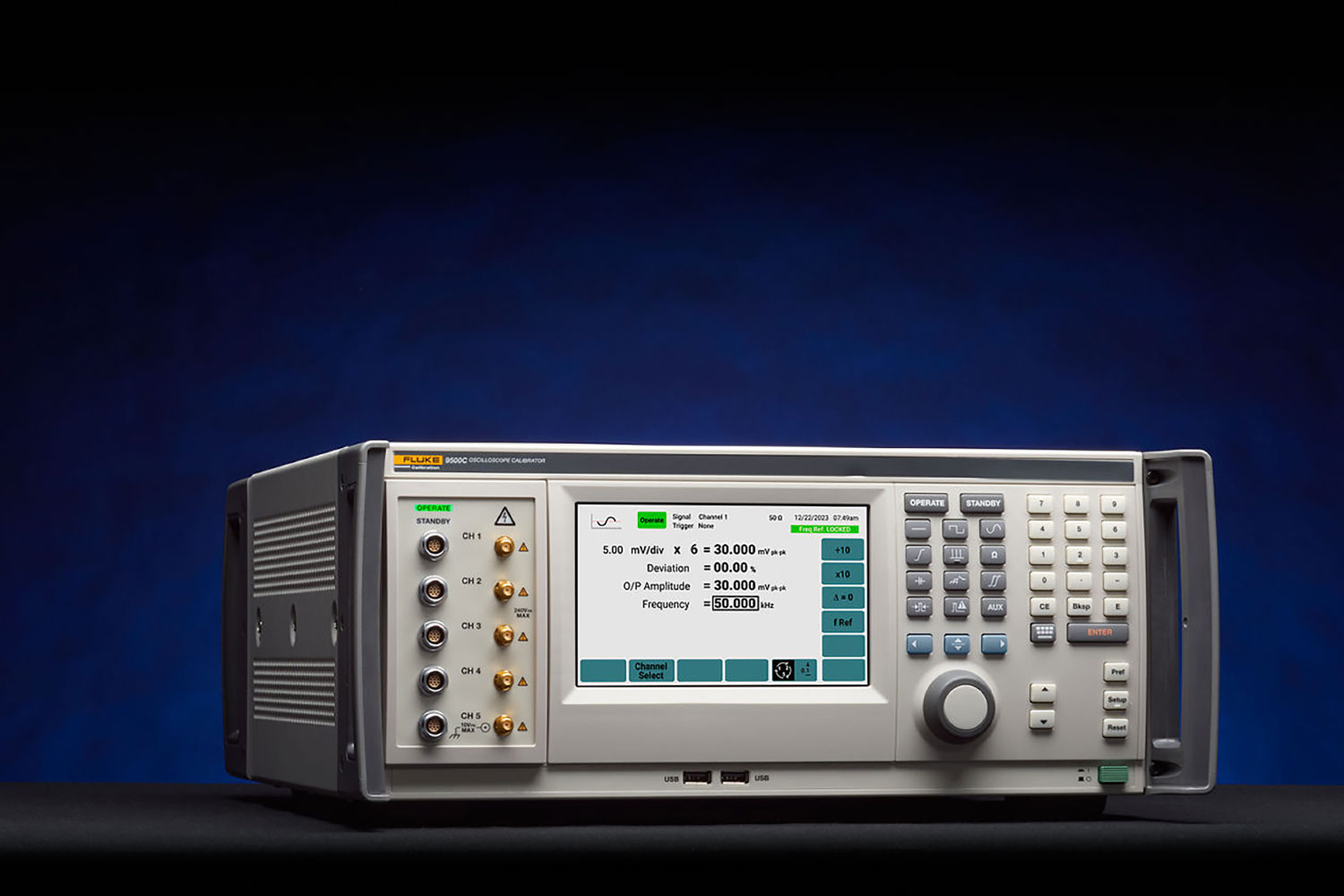
All Fluke scope calibrators provide DC voltage and 1 kHz square wave outputs for testing the gain and offset of DC coupled amplifiers.
- With AC coupling, a square wave signal is injected at 1 kHz, and again the channel’s response is measured against graticule divisions or cursor readings on the display.
Using a low frequency pulse can also provide a rough check of the gross Low Frequency (LF) and High Frequency (HF) response. This is only a very rough test of gross distortion. A result which looks square must still be checked for pulse response and bandwidth.
All Fluke scope calibrators provide a 1 kHz square wave for testing the LF gain of AC coupled amplifiers.
Channel amplifiers’ linearity can be tested by injecting either a DC or a square wave signal, varying the amplitude and checking the changes against the graticule or cursor readings.
Pulse response
Viewing the rise time of pulse fast edges is one of two complementary methods of measuring the response of the vertical channel to pulsed inputs (the amplifier’s bandwidth should also be measured).
Response to fast edges depends on the input impedance of the oscilloscope to be tested. Two standard input impedances are generally in use: 50 Ω and 1 MΩ/(typically) 15 pF. 1 MΩ is the industry standard input, generally used with passive probes. Where the 50 Ω input is provided, it gives optimal matching to HF signals.
To measure the rise time, the pulse signal is injected into the channel to be tested; the trigger and time base are adjusted to present a measurable screen image, and the rise/fall time is measured against the graticule or cursor readings. The observed rise/fall time has two components: that for the applied signal and that for the channel under test. They are combined as the root of the sum of squares, so to calculate the time for the UUT channel, a formula must be used:
UUT rise/fall time = Square root [(Observed time)2 – (Applied signal time)2 ]
In some oscilloscopes the vertical graticule is specially marked with 0%, 10%, 90%, and 100% to make it easy to line up the pulse amplitude against the 0% or 100% marks, then measure the 10%/90% crossing points against marks on the center horizontal graticule line. Many modern DSOs have measurement cursors of functions that make rise time measurements at these same points.
Measurement
In all Fluke models, two different sort of pulses are used:
- Low Edge Function: a low voltage amplitude pulse matched into 50 Ω with a rise/fall time significantly less than 1 ns. When using the formula to calculate the Unit under test (UUT) rise/fall time, the applied signal rise time must be certified at the most-recent calibration of the calibrator, closest to the amplitude of the applied pulse.
- High Edge Function: a high voltage amplitude pulse matched into 1 MΩ with a rise time less than or equal to 100 ns. This function is used mainly to calibrate the response of the oscilloscope’s channel attenuators.
Leading-edge aberration
Aberrations, or overshoot and undershoot, are visible on the display. They often appear at the top end of the edge, before the voltage settles at its final value (which is defined as 100%).
When aberrations are displayed for measurement, they should be within the specification limits. Where the oscilloscope’s aberration specification approaches that of the calibrator, other methods must be used to calibrate.
Channel bandwidth
As well as determining the pulse response by viewing a specimen pulse on the screen, this should be supported by measuring the amplifier’s bandwidth using a ‘leveled sine wave.’ This is done at an input impedance of 50 Ω, to maintain the integrity of the 50 Ω source and transmission system.
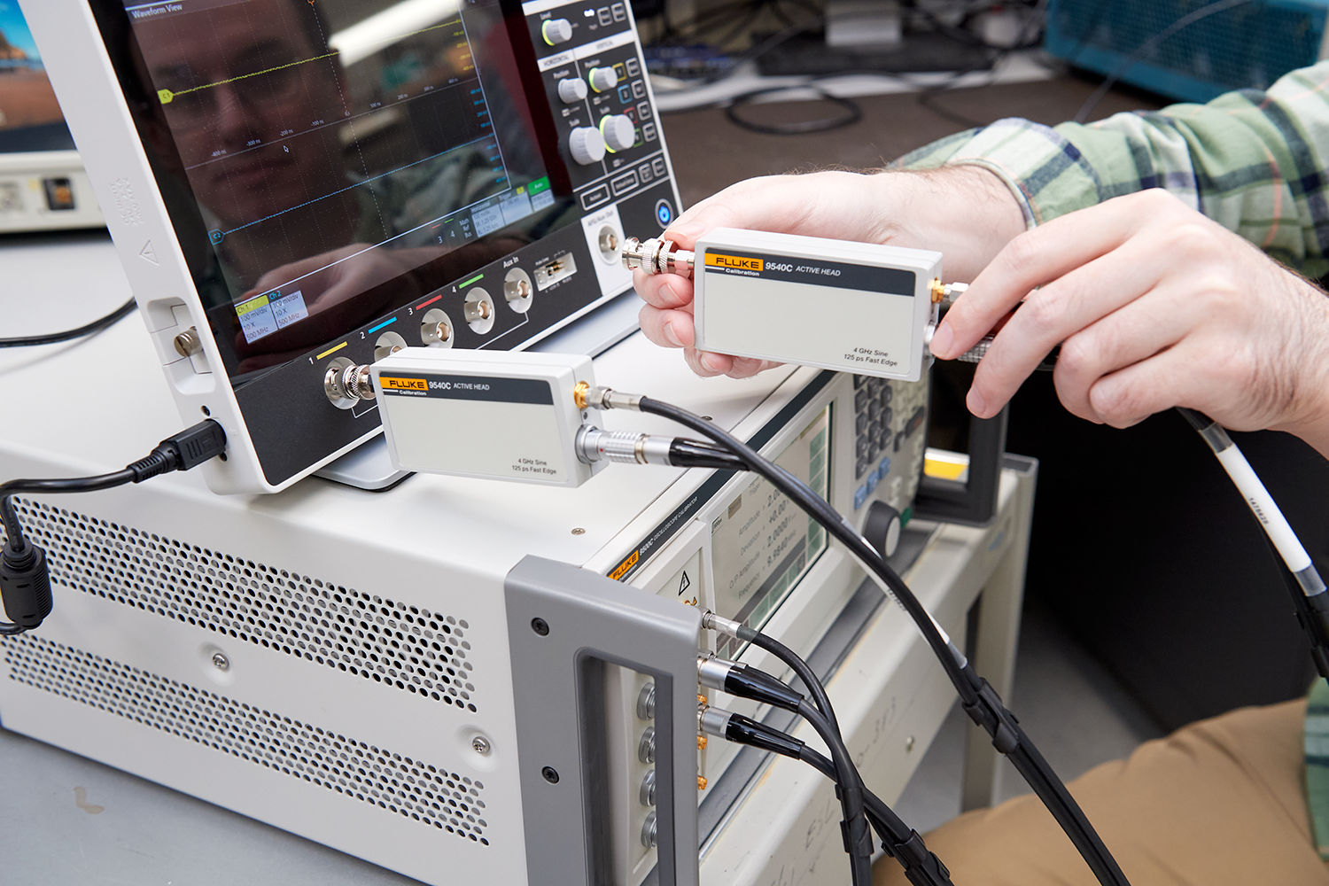
For high input impedance oscilloscopes, an in-line 50 Ω terminator is used to match the line at the oscilloscope input. The in-line 50 Ω could take the form of a separate 50 Ω terminator or be incorporated within an ‘Active’ head—the latter gives the benefit of full automation and requires no additional calibration.

First the displayed amplitude of the input sinusoidal wave is measured at a reference frequency (usually 50 kHz), then the frequency is increased, at the same amplitude, to the specified 3 dB frequency of the channel. The displayed amplitude is measured again.
The bandwidth is correct if the observed 3 dB point amplitude is equal to or greater than 70% of the value at the reference frequency.
If it is needed to establish the actual 3 dB point, the frequency should be increased until the peak-to-peak amplitude is 70% of the value at the reference frequency, then this frequency is close to the 3 dB point.
Continue calibrating
The next steps in the oscilloscope calibration process continue in these articles:
- How to calibrate your oscilloscope for horizontal accuracy
- How to calibrate trigger operation on an oscilloscope
- How to calibrate an oscilloscope for phasing
Return to previous article
- Home
- Products
- New Products
- Electrical Calibration
- RF Calibration
- Data Acquisition and Test Equipment
- Temperature Calibration
- Humidity Calibration
- Pressure Calibration
- Flow Calibration
- Process Calibration Tools
- Calibration Software
- Service and Support
- All Calibration Instruments
- Handheld Test Tools
- Purchase Info
- News
- Training and Events
- Literature and Education
- Service and Support
- About Us


