- Other Fluke companies:
- Fluke
- Fluke Biomedical
- Fluke Networks
- Fluke Process Instruments
Temperature Simulation in Temperature Calibration
Temperature simulation is often usen in you calibrating thermometers for process measurement and control. Unfortunately many technicians are often only doing half the job.
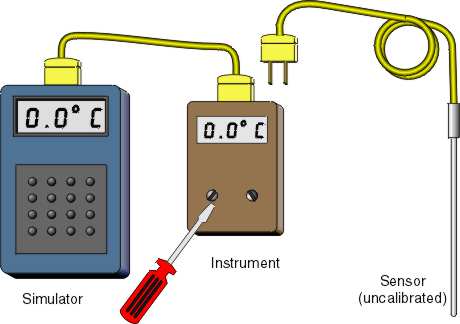
Instrument shops calibrate industrial instruments with a simulator. Simulators produce an electronic signal that duplicates the correct signal made by a theoretically accurate thermocouple or RTD. This method is shown in figure 1.

Once the simulator is connected to your readout or control instrument, you enter the desired output temperatures. You calibrate your instrument against the values entered in the simulator. This process calibrates the instrument to accurately read a sensor that conforms to the industry standard voltage, or resistance versus temperature curves. The calibration, of course, is only good if your sensor matches these industry specs, and as figure 1 illustrates, the sensor is not part of a simulator-based calibration. Since up to 80% of industrial measurement error is normally in the sensor, you’ve got a problem if ISO or other quality standards require you to calibrate for system error.
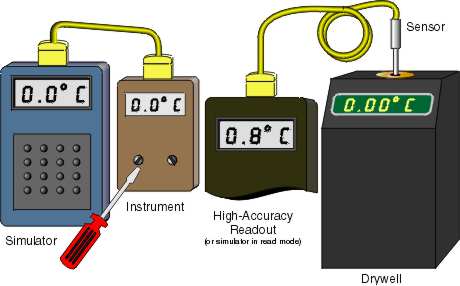
In order to verify sensor compliance with industry standard curves, you’ll have to have another device (i.e. dry-well or Micro-Bath), in addition to the simulator, that generates an accurate temperature for the sensor to read and you to calibrate against. Of course, this temperature must be read by a device that does not contribute significant error to the sensor reading. Figure 2 shows this configuration and the need for two additional instruments in the calibration process.

To avoid using a separate readout, you can buy a simulator that reads temperature accurately as well as generates signals. This is a good alternative if you want to use sensors interchangeably with your instruments and, therefore, really don’t have a “true system” against which to calibrate.
Using sensors interchangeably has a weakness in that sensors can’t be adjusted to meet theoretical standard curves, thus you have to live with the sensor error or reject the sensor. Figure 2 also illustrates this point with the dry-well set to 0.00°C and the sensor reading 0.8°C, a high reading. Although the meter is adjusted for no error at 0°C using the simulator, when the sensor is connected to the instrument the combination of the two produces an overall error of 0.8°C. The system error of this combination is 0.8°C.
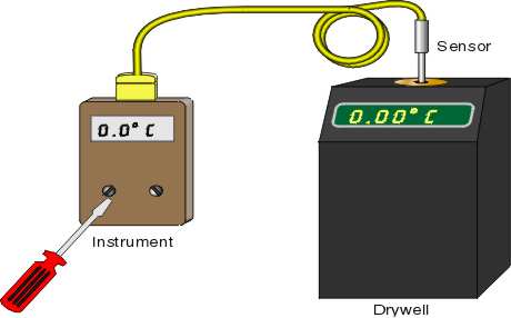
If you are not using sensors interchangeably, then you should be calibrating for system error. System calibration is often less complicated and more reliable than calibration of each component of a system. Figure 3 shows a typical system calibration with the sensor in the dry-well attached to the readout instrument. The instrument is then adjusted for the error found in the combination of components. System calibration assures the highest possible accuracy for industrial thermometers.

- Home
- Products
- New Products
- Electrical Calibration
- RF Calibration
- Data Acquisition and Test Equipment
- Temperature Calibration
- Humidity Calibration
- Pressure Calibration
- Flow Calibration
- Process Calibration Tools
- Calibration Software
- Service and Support
- All Calibration Instruments
- Handheld Test Tools
- Purchase Info
- News
- Training and Events
- Literature and Education
- Service and Support
- About Us

